
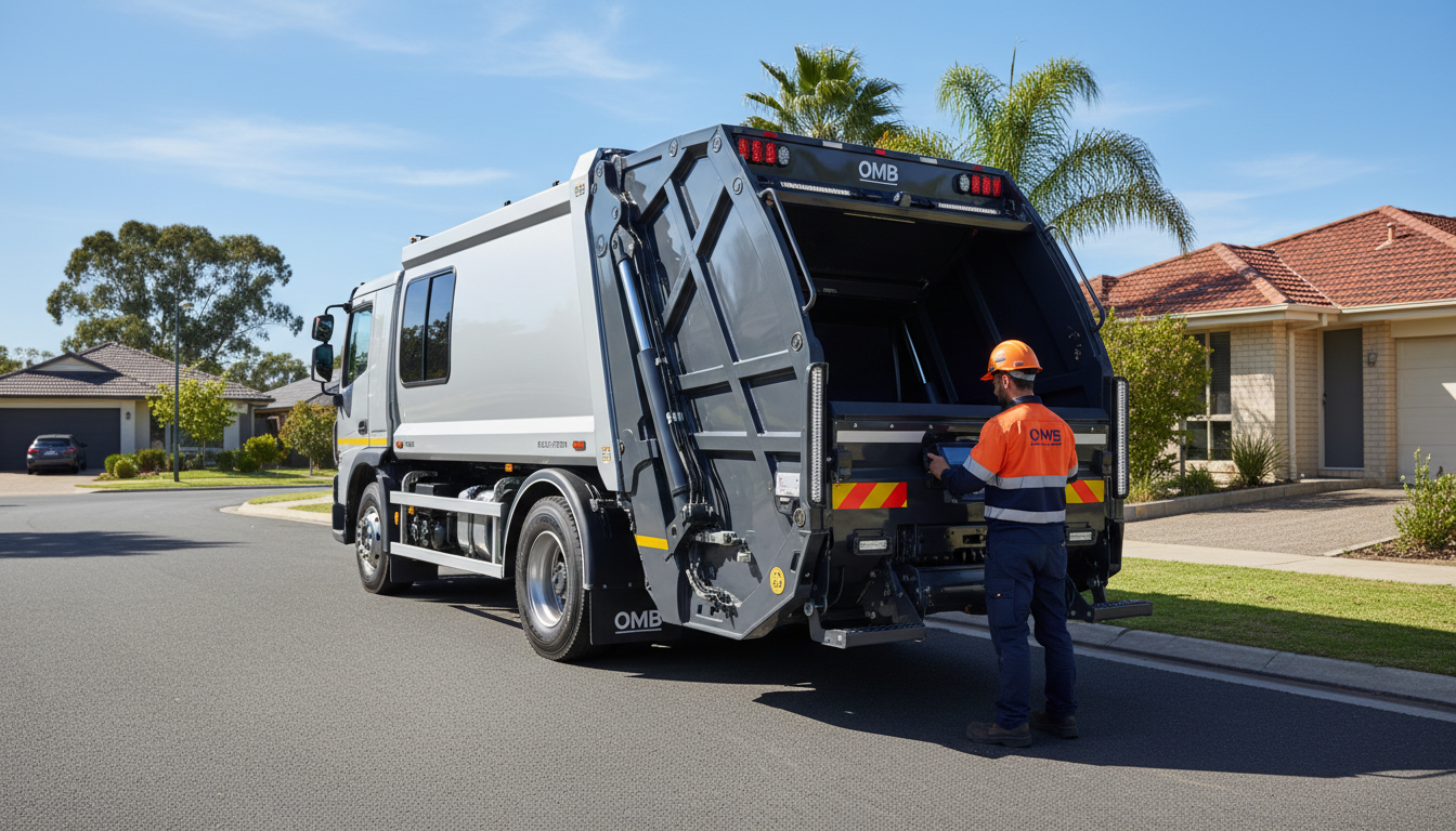
Integrating a rear lift system into a modern waste truck chassis requires precise engineering coordination across hydraulic, electrical, and structural systems. Specifying an OMB rear lift system Australia without understanding PTO interface requirements, hydraulic circuit design, and chassis mounting geometry can result in compromised cycle times, premature component failure, or non-compliance with National Heavy Vehicle Regulator (NHVR) mass distribution limits under the Heavy Vehicle National Law (HVNL). Fleet engineers and procurement managers evaluating rear lift system selection criteria must account for the complete integration pathway from power take-off to bin discharge geometry, ensuring the system operates safely within AS 4024.1 (safety of machinery) and AS/NZS ISO 45001 (occupational health and safety) requirements.
OMB rear lift systems, distributed in Australia by Wastecorp Equipment, are engineered for integration with Isuzu, Hino, and Fuso chassis platforms commonly specified for municipal and commercial waste collection. This technical explainer addresses the critical integration points that determine system performance, operator safety, and regulatory compliance across Australian waste operations.
How OMB Rear Lift Systems Mount to Australian Truck Chassis
OMB rear lift systems mount to the truck chassis via a fabricated subframe constructed from high tensile structural steel, typically grade AS/NZS 3678-350 or equivalent, designed to distribute lifting loads across multiple chassis cross-members. The subframe extends from the rear of the cab to the rear axle centreline, with mounting points positioned to align with the chassis manufacturer’s approved attachment zones. Isuzu FRR and FSR series chassis, for example, specify subframe mounting at designated cross-member locations to maintain chassis warranty compliance and structural integrity under dynamic loading.
Mounting geometry must account for rear overhang limits defined by the chassis manufacturer and NHVR mass distribution requirements. Excessive rear overhang increases leverage on the rear axle, potentially exceeding axle load limits during bin lifting cycles. OMB systems are typically configured with a rear overhang of 1200-1800 mm from the rear axle centreline, depending on bin capacity and chassis wheelbase. The subframe must be engineered to maintain the centre of gravity within the chassis manufacturer’s specified envelope, particularly when lifting 240-litre or 660-litre bins to maximum discharge height.
Chassis rail reinforcement may be required on lighter GVM platforms (under 8000 kg GVM) to accommodate the concentrated loads imposed during bin lifting and compaction cycles. This reinforcement typically involves welded steel plate sections or bolted reinforcement channels extending 600-900 mm forward and aft of the primary subframe mounting points. All welding must comply with AS/NZS 1554.1 (structural steel welding) to ensure fatigue resistance over the operational life of the vehicle.
PTO Integration and Power Take-Off Requirements for OMB Systems
OMB rear lift systems require a power take-off (PTO) interface to drive the hydraulic pump that powers the lifting and compaction circuits. The PTO mounts to the truck’s transmission or transfer case, extracting rotational power from the engine to drive a gear-type or piston-type hydraulic pump. Typical PTO configurations for OMB systems deliver 80-120 litres per minute at 180-220 bar operating pressure, depending on bin capacity, cycle time requirements, and compaction ratio specifications.
Isuzu FRR and FSR series trucks commonly use a transmission-mounted PTO with a six-bolt SAE B or C flange interface, while Hino 300 and 500 series platforms may utilise a split-shaft PTO configuration. The PTO must be matched to the transmission type (manual, automated manual, or automatic) and gear ratio to ensure adequate hydraulic flow without exceeding engine torque limits or causing transmission overheating. Automated manual transmissions (AMT) require PTO engagement interlocks to prevent engagement while the vehicle is in motion, typically integrated via the truck’s CAN bus system.
Hydraulic pump displacement must be calculated to deliver the required flow rate at the engine’s PTO-rated speed, typically 1800-2200 rpm. A 60 cc/rev gear pump operating at 2000 rpm delivers approximately 120 litres per minute, sufficient for a standard OMB rear lift cycle time of 18-25 seconds for a 240-litre bin. Undersized pumps result in slow cycle times and reduced productivity, while oversized pumps increase fuel consumption and hydraulic system heat generation. Wastecorp Equipment specifies PTO and pump combinations based on the chassis platform and operational duty cycle to optimise performance and component longevity.
Hydraulic Circuit Integration: Proportional Valves and Flow Control
OMB rear lift systems utilise closed-centre load-sensing hydraulic circuits with proportional control valves that modulate flow and pressure to the lift cylinders and compaction ram. This configuration provides precise control over bin lifting speed and compaction force, reducing shock loads on the chassis and extending component service life. The hydraulic circuit operates independently from the truck’s steering and brake circuits, requiring a dedicated hydraulic reservoir with a capacity of 80-150 litres, depending on system displacement and cycle frequency.
Proportional valves are electronically controlled via pulse-width modulation (PWM) signals from the in-cab control interface, allowing the operator to adjust lifting speed and compaction force based on waste material density and bin weight. This control architecture reduces hydraulic shock and minimises noise during residential collection routes. The valve block typically includes pressure relief valves set at 220-240 bar to protect cylinders and hoses from overpressure conditions, and load-holding check valves to prevent unintended lowering of the lift mechanism under load.
Hydraulic filtration is critical to system reliability, with OMB circuits typically specifying 10-micron return-line filters and 25-micron suction strainers to prevent contamination of proportional valve spools and cylinder seals. Oil coolers are mandatory on systems with high duty cycles (more than 200 lifts per shift) to maintain hydraulic fluid temperature below 80°C, preventing viscosity breakdown and seal degradation. Integration of the hydraulic circuit must comply with AS 4024.1 requirements for guarding of rotating components, high-pressure hose routing, and emergency stop functionality. Detailed hydraulic system maintenance protocols are essential to sustaining system performance across multi-year operational cycles.
Electrical System Integration and CAN Bus Compatibility
OMB rear lift systems require integration with the truck’s 12V or 24V DC electrical system to power control modules, proportional valve solenoids, and operator interface displays. Electrical integration involves dedicated circuit protection via fused distribution blocks, relay modules for PTO engagement, and wiring harnesses rated for the vibration and environmental exposure typical of waste collection operations. All electrical components must be rated to IP65 or higher to prevent ingress of water and dust during high-pressure wash-down procedures.
Modern OMB systems support CAN bus communication protocols (SAE J1939 or ISO 11898) for integration with the truck’s engine control unit (ECU) and instrument cluster. CAN bus integration enables real-time monitoring of hydraulic system pressure, PTO engagement status, and cycle count data, with fault codes transmitted to the instrument cluster for diagnostic purposes. This integration also allows PTO engagement interlocks to be enforced via the transmission control module, preventing PTO operation when the vehicle is in gear or above a specified road speed threshold.
In-cab control interfaces must be positioned within the operator’s reach while maintaining visibility of the rear lifting zone, complying with AS/NZS ISO 45001 requirements for operator control station design. Control panels typically include momentary rocker switches or joystick controls for lift, lower, and compaction functions, with visual and audible alarms to indicate system faults or overpressure conditions. Emergency stop buttons must be provided at both the in-cab control station and the rear of the vehicle, wired in series to de-energise the PTO and hydraulic system when activated.
Bin Lifting Geometry and Chassis Wheelbase Considerations
Bin lifting geometry is determined by the arc radius of the lift arms, the pivot point location relative to the rear axle, and the discharge height required to clear the hopper or compactor body. OMB rear lift systems are engineered with lift arm lengths of 1200-1600 mm, depending on bin capacity and discharge height requirements. The pivot point is typically positioned 400-600 mm forward of the rear axle centreline to balance lifting leverage against chassis stability during the lift cycle.
Chassis wheelbase directly affects the available space for subframe mounting and the clearance between the lift mechanism and the cab. Short wheelbase chassis (3000-3500 mm) may require compact lift arm configurations or offset pivot points to prevent interference with the cab during bin rotation. Longer wheelbase chassis (4000-5000 mm) provide greater flexibility for lift arm geometry but increase the vehicle’s turning radius, which can be problematic in residential collection routes with narrow streets and cul-de-sacs. Consideration of waste collection truck procurement considerations must include wheelbase selection based on route characteristics and bin lifting requirements.
Discharge height must be calculated to ensure complete bin emptying without material spillage or operator intervention. Standard OMB rear lift systems achieve discharge heights of 1800-2200 mm above ground level, sufficient for most compactor hopper designs. Bin retention mechanisms, typically consisting of hydraulically actuated comb or gripper systems, must securely hold the bin during the lift cycle to prevent dislodgement or rotation. The retention system must accommodate variations in bin design, including wheelie bins with offset axles and commercial bins with reinforced lifting rims.
NHVR Compliance: Mass Distribution and Axle Load Limits
Integration of an OMB rear lift system affects the vehicle’s mass distribution, particularly during bin lifting when the load is positioned aft of the rear axle. The NHVR specifies maximum axle loads based on axle group configuration and tyre ratings, with single axles limited to 6000-6500 kg and tandem axle groups limited to 16500-17000 kg, depending on axle spacing and suspension type. Exceeding these limits during operational cycles can result in infringement notices and vehicle defect notices under the HVNL.
Mass distribution calculations must account for the weight of the rear lift mechanism (typically 400-600 kg for OMB systems), the compactor body or bin tipper hopper (800-1500 kg), and the maximum payload capacity of the system. When a 660-litre bin weighing 250 kg is lifted to discharge height, the effective load on the rear axle increases due to the leverage effect of the extended lift arms. This dynamic loading must be calculated using the chassis manufacturer’s load distribution software or engineering analysis to ensure compliance with NHVR limits.
Wastecorp Equipment provides NHVR compliance documentation for OMB rear lift installations, including mass distribution calculations, axle load analysis, and certification of subframe mounting integrity. This documentation is required for vehicle registration and periodic heavy vehicle inspections conducted under the HVNL. Fleet operators must maintain these records and ensure that operational procedures, including maximum bin weight limits and payload monitoring, prevent axle overloading during collection routes.
Service Access and Maintenance Integration Points
OMB rear lift systems are designed with service access points for hydraulic pump inspection, cylinder seal replacement, and valve block maintenance. The hydraulic pump is typically mounted on the chassis rail or subframe adjacent to the PTO, with access panels or removable guards to facilitate oil level checks, filter replacement, and coupling inspection. Pump service intervals are typically specified at 500-1000 operating hours, depending on duty cycle intensity and hydraulic fluid quality.
Lift cylinders are equipped with replaceable rod seals and piston seals, with service access requiring partial disassembly of the lift arm assembly. Cylinder service is typically required at 2000-3000 operating hours or when visible oil leakage occurs. The valve block is mounted in an accessible location, typically on the subframe or chassis rail, with quick-disconnect fittings to facilitate removal for bench testing or valve spool replacement. All hydraulic hoses are routed with service loops to allow disconnection without draining the entire system, reducing maintenance downtime.
Scheduled maintenance intervals for OMB rear lift systems align with compactor servicing intervals to minimise vehicle downtime and consolidate service activities. Hydraulic fluid replacement is typically required at 2000-hour intervals, with filtration system inspection at 500-hour intervals. Structural components, including subframe mounting bolts, lift arm pivot pins, and bin retention mechanisms, require torque verification and wear inspection at 1000-hour intervals. Wastecorp Equipment provides maintenance schedules and wear component replacement schedules specific to OMB rear lift configurations, ensuring fleet operators maintain system reliability and compliance with AS 4024.1 safety requirements.
When OMB Integration Suits Your Operation
OMB rear lift systems are suited to operations requiring high cycle frequency, precise bin handling, and integration with compactor bodies for residential or commercial waste collection. The proportional valve control architecture provides smooth, controlled lifting cycles that reduce noise and shock loading, making OMB systems appropriate for residential routes with noise restrictions and high-density collection schedules. The closed-centre hydraulic circuit design minimises parasitic power losses, improving fuel efficiency on routes with frequent stop-start cycles.
Fleet operators evaluating rear lift versus skip loader system comparison should consider OMB rear lift integration when bin standardisation is established across the collection route and compaction is required to maximise payload density. OMB systems are less suited to operations requiring mixed bin sizes or skip bin collection, where hook lift or cable lift systems provide greater operational flexibility. Chassis compatibility, particularly on Isuzu FRR/FSR and Hino 300/500 platforms, is a critical factor in system selection, as these chassis provide the wheelbase, GVM, and PTO interface configurations optimised for OMB integration.
Wastecorp Equipment, as the official distributor for OMB in Australia and a member of the Waste Contractors and Recyclers Association of NSW (WCRA), provides engineering support for chassis selection, hydraulic circuit design, and NHVR compliance documentation to ensure successful OMB rear lift integration across municipal and commercial waste fleets.
Frequently Asked Questions
What PTO output is required for OMB rear lift systems in Australia?
OMB rear lift systems typically require a PTO output of 80-120 litres per minute at 180-220 bar operating pressure, depending on bin capacity and cycle time requirements. The PTO must be matched to the truck’s transmission type and hydraulic pump displacement to ensure adequate flow without exceeding engine torque limits under Heavy Vehicle National Law (HVNL) mass compliance. Isuzu FRR and Hino 500 series chassis commonly use transmission-mounted PTO configurations with six-bolt SAE B or C flanges, while automated manual transmissions require CAN bus integration for PTO engagement interlocks. Wastecorp Equipment specifies PTO and pump combinations based on chassis platform and operational duty cycle to optimise performance and fuel efficiency.
Are OMB rear lift systems compatible with Isuzu and Hino truck chassis?
OMB rear lift systems integrate with Isuzu FRR/FSR and Hino 300/500 series chassis through standardised subframe mounting and PTO interfaces. Chassis wheelbase, rear overhang, and GVM ratings must be specified to ensure bin lifting geometry clears the cab and maintains axle load distribution within National Heavy Vehicle Regulator (NHVR) limits. Short wheelbase chassis (3000-3500 mm) may require compact lift arm configurations to prevent cab interference, while longer wheelbase platforms (4000-5000 mm) provide greater flexibility for lift arm geometry but increase turning radius. Wastecorp Equipment provides chassis compatibility analysis and subframe engineering to ensure successful OMB integration across Australian truck platforms, maintaining chassis manufacturer warranty compliance and HVNL mass distribution requirements.
How do OMB rear lift hydraulic systems integrate with existing truck circuits?
OMB systems use closed-centre load-sensing hydraulic circuits with proportional control valves that operate independently from the truck’s steering and brake circuits. Integration requires a dedicated hydraulic reservoir (typically 80-150 litres), oil cooler, and filtration system meeting AS 4024.1 safety requirements to prevent cross-contamination and maintain system pressure integrity. The hydraulic circuit includes 10-micron return-line filters and 25-micron suction strainers to protect proportional valve spools and cylinder seals from contamination. Pressure relief valves are set at 220-240 bar to protect system components, and load-holding check valves prevent unintended lowering under load. All hydraulic hoses are routed with service loops and quick-disconnect fittings to facilitate maintenance without draining the entire system.
What electrical integration is required for OMB rear lift control systems?
OMB rear lift systems require 12V or 24V DC power supply with dedicated circuit protection, integrated with the truck’s electrical system via relay modules. Modern OMB systems support CAN bus communication for diagnostics and cycle monitoring, with control interfaces mounted in-cab to comply with AS/NZS ISO 45001 operator safety standards. CAN bus integration (SAE J1939 or ISO 11898 protocols) enables real-time monitoring of hydraulic pressure, PTO engagement status, and fault code transmission to the instrument cluster. In-cab control panels include momentary rocker switches or joystick controls for lift, lower, and compaction functions, with emergency stop buttons provided at both the control station and the rear of the vehicle. All electrical components are rated to IP65 or higher to withstand high-pressure wash-down procedures and environmental exposure typical of waste collection operations.
Wastecorp Equipment supplies OMB rear lift systems with full chassis integration support, hydraulic circuit design, and NHVR compliance documentation for Australian waste fleets.
Official distributor for MEC and OMB. Member of the Waste Contractors and Recyclers Association of NSW.

 Member of Waste Contractors and Recyclers Association of NSW.